Modeling based on degenerated shell finite element for the. The torque is often relatively constant at steady state operation.
How Sighting Boring And Alignment Of Ship S Propeller Shaft Is Done
Methodicaldesign engineering is the heuristic use of newly developed and established methods within the engineering design process including theory-based and industry best practice strategic and tactical formalized and intuitive methods.

. Solid and hollow Propeller shaft design. B Solution uses an integral pinion three shaft shoulders key and keyway and sleeve. Three forged schemes have been determined according to the shape of the forged and the conditions of the existing hydraulic presses in the factory.
Features And Design Of Propeller Shaft Forging Process 1 Option 1 using 800mm upper. Determine the shaft rotational speed. Dp 125 x 400135 dp 500 mm Design of Intermediate Shaft d The intermediate shaft is subjected to bending.
Much of the preparation is carried out during the Design stage. The composite drive shaft made up of high modulus material is designed by using CAD software and tested in ANSYS. Features And Design Of Propeller Shaft Forging Process 1 Option 1 using 800mm upper.
1 Option 1 using 800mm upper flat anvil and lower platform compaction process. Design of Propeller Shaft dp Since the propeller shaft is subjected to both bending moment due to propeller weight and twisting moment diameter of propeller shaft dp 25 extra then the designed by pure torsion. The housing locates the bearings on their outer rings and receives.
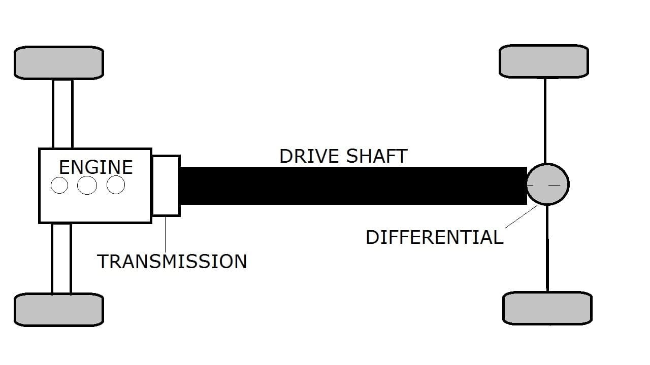
Determine the dimensions of the power transmitting devices and other components to. Design procedure flow chart for a shaft with fluctuating loading. Construction of propeller shaft Propeller shaft or Cardan shaft is a mechanical component of transmissionfor transmitting torque and rotation.
The traditional approach to the detailed design of propeller blades has been that the propeller blade sections are designed for the mean inflow conditions around the circumference at a set of specific radii in the propeller disc. One can overcome the difficulties encountered in designing any product by using automation. As blades are added to the design they increase the.
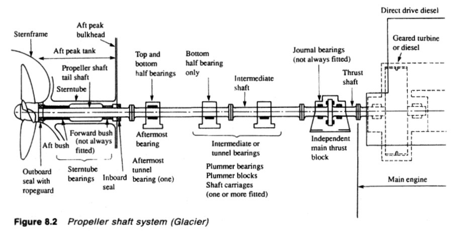
In this paper six automotive propeller shafts made of different materials are designed. Alignment of these propulsion units with the prime movers does not follow the conventional shaft sighting and alignment procedure. DESIGN OF SHAFTS The shaft may be designed on the basis of 1.
To start with we will take the diameter of the driving shaft as 50 mm. As blades are added to the design they increase the. Rigidity and stiffness In designing shaft on the basis of strength the following cases may be consider 1.
The disconnect-design PTU has the ability to internally engage and send power and torque to the rear propeller shaft activating AWD mode. Nearly all marine props are of a screw propeller design and are designed with a variety of materials typically aluminum steel or brass. It usually used to connect other components of a drive train that cannot be connected directly because of distance between them.
Our main aim is to study its design procedure along with finite element analysis some important parameter will be obtained. The shaft-line is modeled along all possible conditions from Drydock to the Afloat stage for all probable Hull. The idea is to automate the process of calculation and generation of 2D drawing of Marine propeller shaft.
The reality is that there are many factors which can affect and alter alignment during building and. Finite element modeling based on shell element is used in the eigenvalue analysis. Features And Design Of Propeller Shaft Forging Process.
Determine the power or torque to be transmitted by the shaft. Systematic and methodical procedures overlap but are not co-incident. Shafts subjected to twisting moment only.
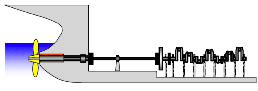
The simplistic view of the main propulsion shaft installation is that the system is set up with initial straight alignment and remains in that state during the lifetime of the ship unless affected by accident or wear. The propeller design process therefore should be balanced with a global hull vibration analysis based on forced inputs from the propeller and cavitation observations to assure that vibration and erosion problems are not overlooked in the name of efficiency. The Theory Of Shaft Alignment.
Propeller Design Process An Overview Sciencedirect Topics The propeller shaft of the ship is connected to large motors which can be DC or AC driven also known as propulsion motors. Shaft subjected to combined twisting moment and bending moment. Length of shaft L1250 mm Inclination angle θ2 Deg.
To check the design of propeller shaft mathematically with a conventional material. Optimize the Number of Blades. Propeller shaft consistof one or several cardan shafts or cardan hinges.
A Choose a shaft configuration to support and locate the two gears and two bearings. Shaft subjected to bending moment only. Density p 7600 Kgm3 Yield stress in shear Ys 370 Mpa Rotational speed N 6500 RPM Youngs modulus E 207000 Mpa Shear modulus G 80000 Gpa Solution.
The propeller shaft. A lesser amount of blades tends to equal a higher theoretical efficiency while a larger number increases the propulsion. 2 Option two using 900mm upper and lower V-shaped anvil.

Propeller Shaft Arrangement 6 Download Scientific Diagram
2

Pdf Design Optimization Of Automotive Propeller Shafts

Propeller Shaft Drive Shaft A Universal Joint 2 Major Types And Functions Of The Propeller Shaft
Propeller Shaft Definition Characteristics Construction Or Parts Types Material Advantages Application Notes Pdf

Cad And Finite Element Models Of The Propeller Shaft A Cad Model And Download Scientific Diagram

Schematic Diagram Of The Propeller Shaft For A Rear Wheel Driving Vehicle Download Scientific Diagram
Propeller Shaft Bearings Various Type
0 comments
Post a Comment